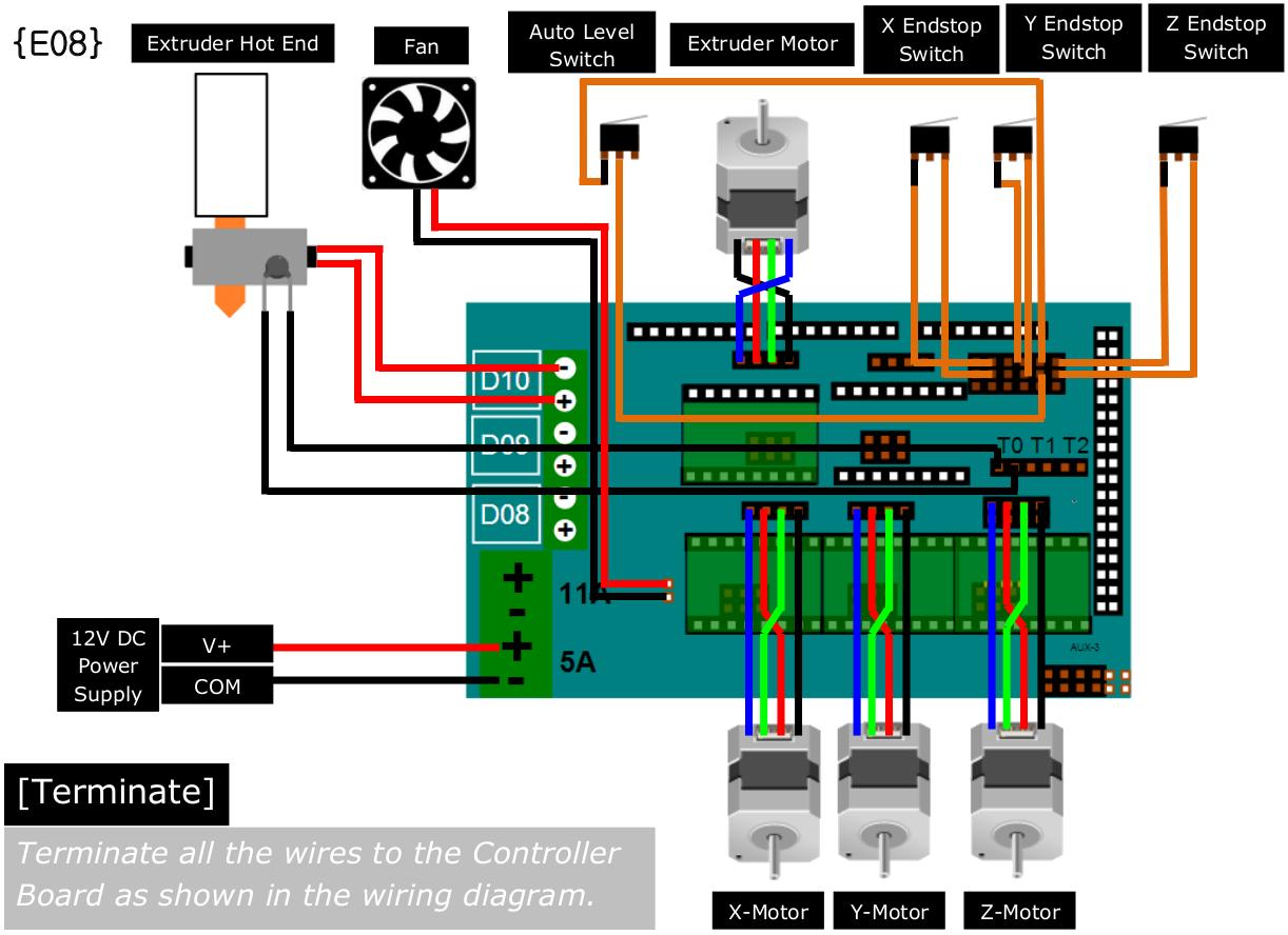
 This is the diagram for wiring the stepper motors to a RAMPS shield. I am a bit confused. I thought that each pair of leads (left to right pairs) on the groups of four were leads to a single winding. Why would they want to swap leads (chaining windings together?) on the main drive motors? Note that all of these driver boards have all three jumpers installed. AFAIK, this setting just made steps smaller.
Also, why swap outside leads on the extruder motor?
Leads on the RAMPS board are labeled (in order), 2B 2A 1A 1B. I was thinking that 1 and 2 refer to windings, and A and B refer to which side of the winding.
My NEMA17 motors have Blue, Yellow, Green, Red wires (in that order). How might that correspond to the Blue, Green, Red, Black wires shown for these motors? Is it possible that the flipping is only needed for their brand of motor, and not for mine? If their brand of motor is different from mine, could the swapping be necessary to put the leads for each winding on the appropriate pins, whereas for my brand the swap is unnecessary? Their drawing might make sense if the motor did not put leads for the same winding next to each other.
On my motors, the Blue and Yellow leads show 2.7 Ohms, and the Red and Green leads show 2.7 Ohms, so those look like winding pairs. (Blue or Yellow) to (Red or Green) show no connection. My best guess is that I don’t need any “wire flipping” for these motors to a RAMPS board. If the direction is wrong, I can just flip the plugs over, right?