Filament Spool Holder


spoolHolderThe following drawing is for a laser-cut thin-plywood holder for 3D printer filament spools.  Just get some 1/2″ PVC pipe or conduit with endcaps for an axle to hold the spools.

When cutting this design in cheap 5mm furniture backing, there were problems with the warping of the stock.  Our laser cutter needs a very flat surface to cut.  I have had to split the design into smaller cuts, which fit on smaller pieces of stock.  The warping error across a small piece of stock can be much less than the warping across a piece of stock large enough for the entire design.

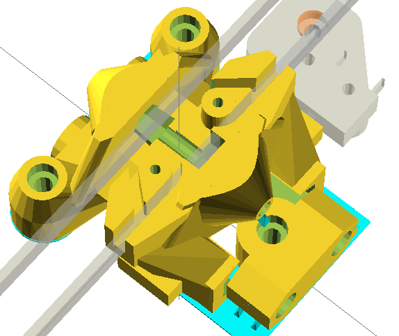
The drawing was split into the


bottom and edge
parts,

which should be cut once, and the


triangular side panel
,

which should be cut twice.


I posted this picture thinking the number of clamps I was using was silly.

clamps
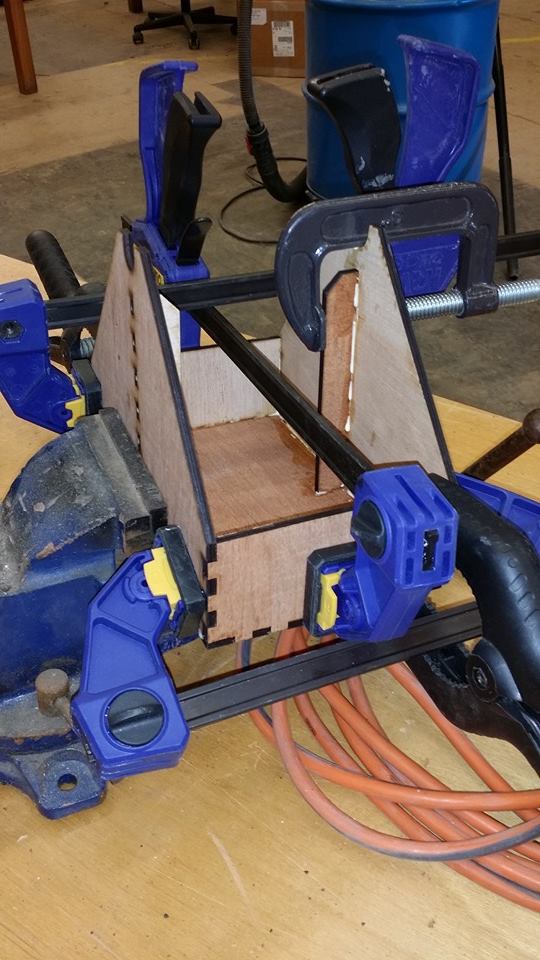
I was informed by a pro that this is actually a proper procedure.

Extruder Motor Mount

bowdenExtruderMount

Installed new Bowden extruder motor mount to vertical frame leg.  Bracket has very tight tolerance to the NEMA17 motor body, so that the motor almost snaps into the mount.  The attachment is actually very solid, even though it is made by wrapping some cable ties around the motor in an “X” pattern.  It mounts to the 15mm wide extrusion rail with two 8mm M3 hex-head bolts, and two standard M3 nuts in the rail.

Clearance from rail is enough to allow linear slider wheels to pass by.

Drawing is available from my github area.

Stepper motor wiring

WiringThis is the diagram for wiring the stepper motors to a RAMPS shield.  I am a bit confused.  I thought that each pair of leads (left to right pairs) on the groups of four were leads to a single winding.  Why would they want to swap leads (chaining windings together?) on the main drive motors?  Note that all of these driver boards have all three jumpers installed.  AFAIK, this setting just made steps smaller.

Also, why swap outside leads on the extruder motor?

Leads on the RAMPS board are labeled (in order), 2B 2A 1A 1B.  I was thinking that 1 and 2 refer to windings, and A and B refer to which side of the winding.

My NEMA17 motors have Blue, Yellow, Green, Red wires (in that order).  How might that correspond to the Blue, Green, Red, Black wires shown for these motors?  Is it possible that the flipping is only needed for their brand of motor, and not for mine?  If their brand of motor is different from mine, could the swapping be necessary to put the leads for each winding on the appropriate pins, whereas for my brand the swap is unnecessary?  Their drawing might make sense if the motor did not put leads for the same winding next to each other.

On my motors, the Blue and Yellow leads show 2.7 Ohms, and the Red and Green leads show 2.7 Ohms, so those look like winding pairs.  (Blue or Yellow) to (Red or Green) show no connection.   My best guess is that I don’t need any “wire flipping” for these motors to a RAMPS board.  If the direction is wrong, I can just flip the plugs over, right?

New design for Delrin Wheel carriage for Kossel-mini delta 3D printer

Just finished a drawing for my latest delrin roller based carriage for a delta 3D printer.  This one uses hardware-free toothed belt clips.  You should be able to attach the belt with no tools or hardware.  Just wrap the belt, teeth toward the “teardrop”, such that the teeth mesh when the belt re-joins at the pointed end of the teardrop.  Insert this little teardrop shaped belt loop around the teardrop post, and it should hold tight.

delta carriage

Delrin wheel based carriage for Delta printer