It seems to me that we may be getting problems with calibration overfits on deltabots (delta 3D printers) by relying too much on bed probes.
Let’s assert that the bed has a slight tilt. When we calibrate endstop offsets, we correct for this tilt. However, it was not the endstop position that was in error, it was the mechanical alignment of the bed in the build. The bed was not exactly perpendicular to the towers.
When we correct this error by an endstop adjustment, we actually impose a tilt on the printing plane, which has this distortion in XY:

The length of the error line indicators is 10x the actual error. We see that a 1mm endstop offset error creates a varying positional shift from about .25 to 1.1mm across the print bed. This could cause a scale/position error of about 0.75mm. This is significant when printing parts for other machines.
I propose that we adjust endstops (for tilt) and MEAN delta radius by bed probes. The bed probes are good at detecting these tilts and bowl/dome errors. Unfortunately, the distortion from a tower position looks very similar to the distortion of a tilt. They are hard to discriminate by bed probe data. I would farther propose that we calibrate Delta Rod-length, and individual tower position deviation (and printer spread) from measurements of test prints, since these scaling measurements are more sensitive to rod-length and tower position errors than the bed-probes.
At some point, it might do the trick to simply add some XY position sensors to do this scaling calibration and re-check. Perhaps just endstops on each tower that the effector head can bump into during calibration tests. This would give us a physical signal, where if the endstops were calibrated, we could compute XY-plane scale errors without the need for cumbersome calibration prints.
Last night I did some research, and came across this thesis from 1996. It appears that deltabots are fairly new. The first ones showing up in the mid-80’s, and their calibration still being the subject of Ph.D. dissertations in 1996. I found another literature review paper from 2010, which makes it look like delta (parallel) robot calibration is still an active area of research.
Luckily, my technique of developing a kinematic model with some parameters, adding error to these parameters, simulating the results, and measuring MSE w.r.t. measurements as an optimization metric is standard procedure. What is unique to my work vs. these papers is that I have a very simple 5-9ish parameter model, which can be optimized by a simple brute-force simplex search, where these papers usually have 20-60 parameter models that need fancy optimizations (Lovenburg-Marguadt etc..) that require Jacobians and Hessians. So where they do real math to model things, I just do a simple numerical simulation, and am getting reliable convergence.
The above suggestion of splitting the parameters into groups and solving separately from different types of measurements has the promise of remaining solvable by simple numerical methods, converging in a reasonable number of steps.
Oct, 18, 2014… Making progress on a full 3D calibration procedure. This one combines measurements of prints of this test object
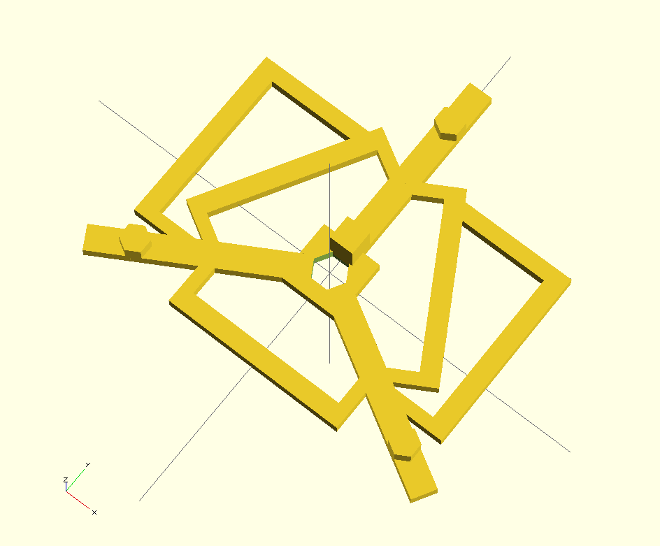
 with bed probes to get a single best fit calibration set. Residual bed leveling error is removed with a best-fit bed level polynomial, order 2. I already have changes to Marlin at https://github.com/Mr-What/Marlin, where the util folder has my new calibration code. Basic simplex search over 8 calibration parameters seems to be converging well. Still going through procedure a few more times to make sure I have all the steps nailed down. Not done yet, but perhaps this weekend.