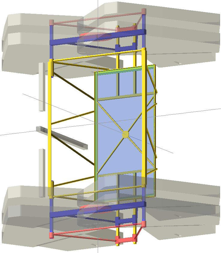
Started design of central basket for steel version.
Still working on leg linkage design.
Thinking about ways to use steel bearings.
The main pivot on the axles is harder.
If we can find very large bearings, we can use them, but we will need 3-4 large bearings per leg.
Author Archives
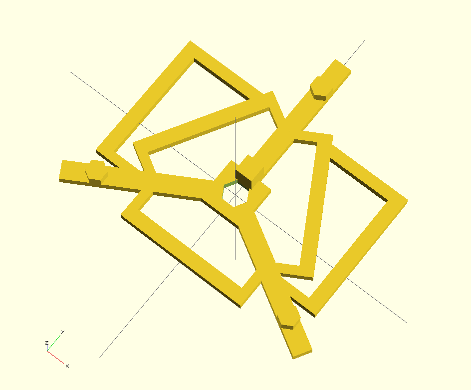
Updated 3D printed design
Have been working on improved 3D printed design.
Assembly process is being documented for release.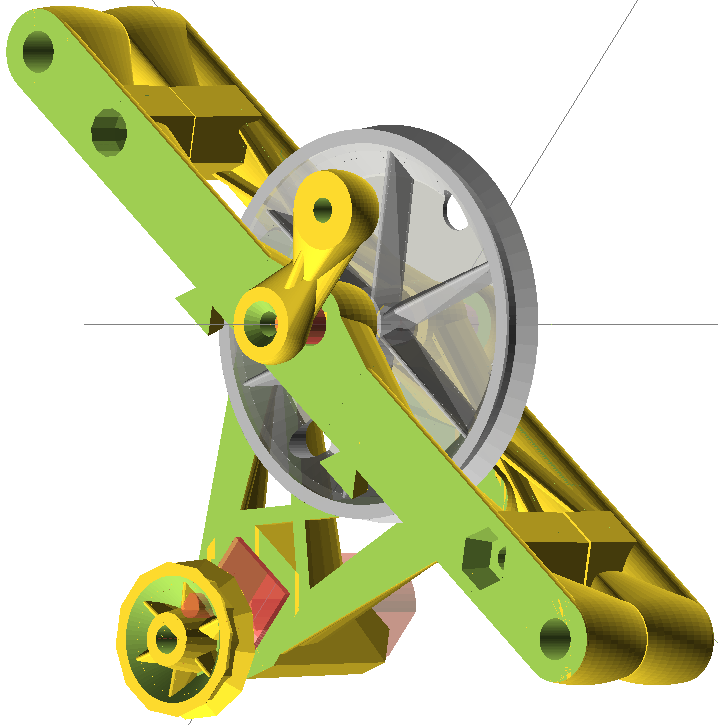
Deltabot calibration overfits
It seems to me that we may be getting problems with calibration overfits on deltabots (delta 3D printers) by relying too much on bed probes.
Let’s assert that the bed has a slight tilt. When we calibrate endstop offsets, we correct for this tilt. However, it was not the endstop position that was in error, it was the mechanical alignment of the bed in the build. The bed was not exactly perpendicular to the towers.
When we correct this error by an endstop adjustment, we actually impose a tilt on the printing plane, which has this distortion in XY:

The length of the error line indicators is 10x the actual error. We see that a 1mm endstop offset error creates a varying positional shift from about .25 to 1.1mm across the print bed. This could cause a scale/position error of about 0.75mm. This is significant when printing parts for other machines.
I propose that we adjust endstops (for tilt) and MEAN delta radius by bed probes. The bed probes are good at detecting these tilts and bowl/dome errors. Unfortunately, the distortion from a tower position looks very similar to the distortion of a tilt. They are hard to discriminate by bed probe data. I would farther propose that we calibrate Delta Rod-length, and individual tower position deviation (and printer spread) from measurements of test prints, since these scaling measurements are more sensitive to rod-length and tower position errors than the bed-probes.
At some point, it might do the trick to simply add some XY position sensors to do this scaling calibration and re-check. Perhaps just endstops on each tower that the effector head can bump into during calibration tests. This would give us a physical signal, where if the endstops were calibrated, we could compute XY-plane scale errors without the need for cumbersome calibration prints.
Last night I did some research, and came across this thesis from 1996. It appears that deltabots are fairly new. The first ones showing up in the mid-80’s, and their calibration still being the subject of Ph.D. dissertations in 1996. I found another literature review paper from 2010, which makes it look like delta (parallel) robot calibration is still an active area of research.
Luckily, my technique of developing a kinematic model with some parameters, adding error to these parameters, simulating the results, and measuring MSE w.r.t. measurements as an optimization metric is standard procedure. What is unique to my work vs. these papers is that I have a very simple 5-9ish parameter model, which can be optimized by a simple brute-force simplex search, where these papers usually have 20-60 parameter models that need fancy optimizations (Lovenburg-Marguadt etc..) that require Jacobians and Hessians. So where they do real math to model things, I just do a simple numerical simulation, and am getting reliable convergence.
The above suggestion of splitting the parameters into groups and solving separately from different types of measurements has the promise of remaining solvable by simple numerical methods, converging in a reasonable number of steps.
Oct, 18, 2014… Making progress on a full 3D calibration procedure. This one combines measurements of prints of this test object
 with bed probes to get a single best fit calibration set. Residual bed leveling error is removed with a best-fit bed level polynomial, order 2. I already have changes to Marlin at https://github.com/Mr-What/Marlin, where the util folder has my new calibration code. Basic simplex search over 8 calibration parameters seems to be converging well. Still going through procedure a few more times to make sure I have all the steps nailed down. Not done yet, but perhaps this weekend.
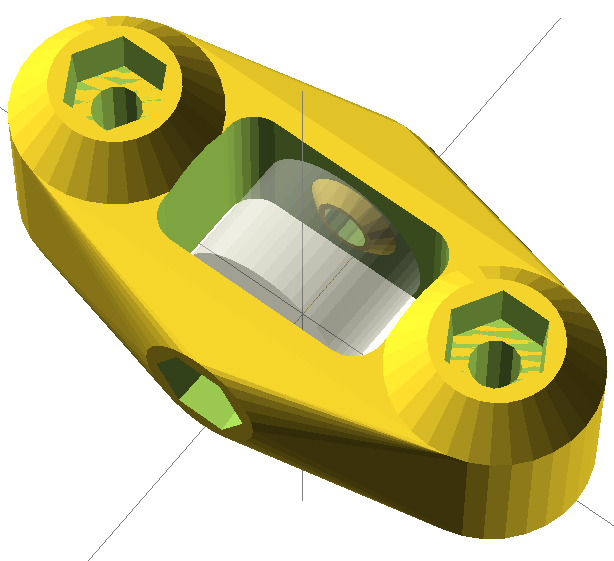
Low Impact Probe idea
I have been finding a problem with a low-pressure probe switch for my deltabot. A few days ago I attended an AdaFruit hangout where Limor Fried mentioned using magnets as contacts. Then I recall somebody on Hackaday or Make doing a 3-contact probe that they used to probe a coin.
Then… I figured that combining the two ideas might make an excellent low-pressure contact probe.

Original drawing source is at http://birenboim.com/tmp/needleProbe.scad with render http://birenboim.com/tmp/needleProbe.stl.zip
Blue disks are magnets. Darker gray-blue are pins. Red are wires. Yellow are insulators. (acrylic? Machined nylon?)
All in a (smoky) case.
Upper plate, glued to probe pin is (somewhat) free floating.
The magnets should attract the pins and help keep the probe aligned and centered. When any one of the magnet/pin contacts is broken, the switch will open.
Could be an excellent high-sensitivity, low force probe.
I have, at least, two problems:
1) I need a very thin, flexible wire for the upper lead.
2) I need to find a way to connect leads to the magnets.
Soldering magnets could be problematic. Conductive glue?
Any suggestions?
Would such a probe be valuable to you?
Calibration after new carriages and belt tensioners

New carriages, with the hardware-free belt catches were installed. Along with these carriages, there was a design change to suspend pulley holders from the top of the printer by two screws. These screws can be used to adjust tension, without altering the attachment of the printer top to the frame.
These changes seem to have been an improvement. I can still see criss-cross pattern on the bed probe, but barely.

As near as I can estimate, the problem has been reduced by a factor of 4-5 in the re-build. The above data came from the standard auto bed-leveling probe. I used this data for initial calibration, but then returned to my more-detailed random bed probe to refine calibration.
Top brace for Kossel Mini
It took a while for me to do the math to get this one correct, so I’m posting my drawing for a top triangle brace for a Kossel-mini.
There are extra holes near the corners to hold belt tensioners for the top pullies.
Automatic Extruder Fan Settings for Marlin
I was not able to get a clear description on how to set up the extruder fan to turn on and off automatically when the extruder is hot. In Configuration_adv.h :
- Set FAN_KICKSTART_TIME to a large value like 2000. Two seconds to spin up a fan won’t be an issue at temperature-change timescales. Give it plenty of time at full power to spin up.
- Set EXTRUDER_0_AUTOFAN_PIN to 9 to use the D9 high-power output port from the RAMPS 1.4 board.
- Set EXTRUDER_AUTO_FAN_SPEED to an appropriate speed, usually around 128 to 255.
Unfortunately, this is compiled in, so you will need to experiment to see how much fan speed is necessary
to keep the extruder cool and/or provide sufficient cooling for the plastic being deposited.
In pins.h:
- Set FAN_PIN to -1 to disable old FAN_PIN usage
I’m not sure what FAN_PIN was and what it did, but it seems to be incompatible with using the automatic temperature-based fan settings.
It appears that when FAN_PIN is used, this is the pin controlled by the M106 Sxxx setting.
I think that M106 no longer does anything when using EXTRUDER_0_AUTOFAN_PIN to control the extruder fan.
It just runs at the one preset speed set by EXTRUDER_AUTO_FAN_SPEED when the extruder is hot.
Calibration tools for Delta 3D printers
I completed some basic documentation for my delta printer calibration scripts so that others can try them out.

You will need a machine with octave (or MATLAB) installed, and perl. These tools use the command line, and command line commands in octave (or MATLAB).
I have recently become aware of a project which does automatic calibration updates to many more parameters than I alter as part of the Marlin firmware. It looks very promising, but I have not tried it yet.
If you wish to try my more conservative calibration technique, I think it is a vast improvement over most of the procedures outlined in various HOWTO’s and Wikis. If you have the automatic bed-leveling probe running on your Marlin firmware (code G29), these scripts should allow you to perform a very good calibration on a typical deltabot in about 3-4 iterations, and taking far less than an hour of your time.
A minor calibration re-check should take no more than 10 minutes.
My technique is not computationally efficient, and must be done on a general purpose computer. It usually takes several minutes to estimate calibration parameter updates.
Insulating extruder hot-end with Melamine foam
I am happy to report that insulating a hotend with Melamine foam seems to be a success. , at least at PLA temperatures (around 185C).
Melamine foam is commonly available as a product like Mr. Clean’s Magic Eraser, or generic equivalents. It can be very affordable, around $1 for a piece about the size of a kitchen sponge. Perhaps less in bulk.
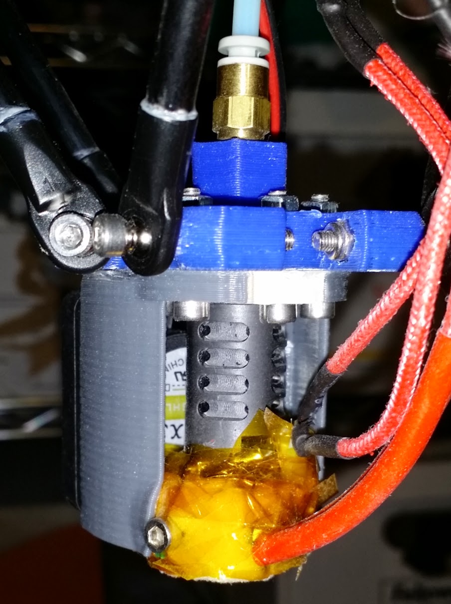
It seems to allow my hotend to stay within about 1/2C of the commanded temperature even while printing with a blower.
Another finding of note is that I was not able to get the hotend to work with the supplied 3 to 5W resistors as heaters. They tended to burn out. These ceramic heater devices seem to work fine. It could be just because the thermal contact with the ceramic heater is better than with the resistor, since I did not attempt to use thermal grease.
Box for RAMPS board


I have a laser cut drawing for a box to hold an Arduino Mega with RAMPS 1.4 stepper motor control board in 3mm acrylic, as are commonly used on 3D printers and GRBL systems.
This box does not include vents or fan mounts (yet). You can add these yourself to match your cooling system.
You will need to cut two copies of this drawing for a full 6-sided box. You can delete any mounting/access holes that you do not want in one of the copies. e.g. Cut one copy as is for power, USB, reset, and Arduino mount holes. Make another copy of the drawing to cut with all holes deleted for the opposing plate.
The source code starts with https://github.com/Mr-What/kossel/blob/master/boxRAMPS200x200.pl
The following drawing is for mounting hardware and vent holes to place a gamma28 blower motor on the RAMPS1.4 box for cooling.