Bowden Extruder hot-end setup

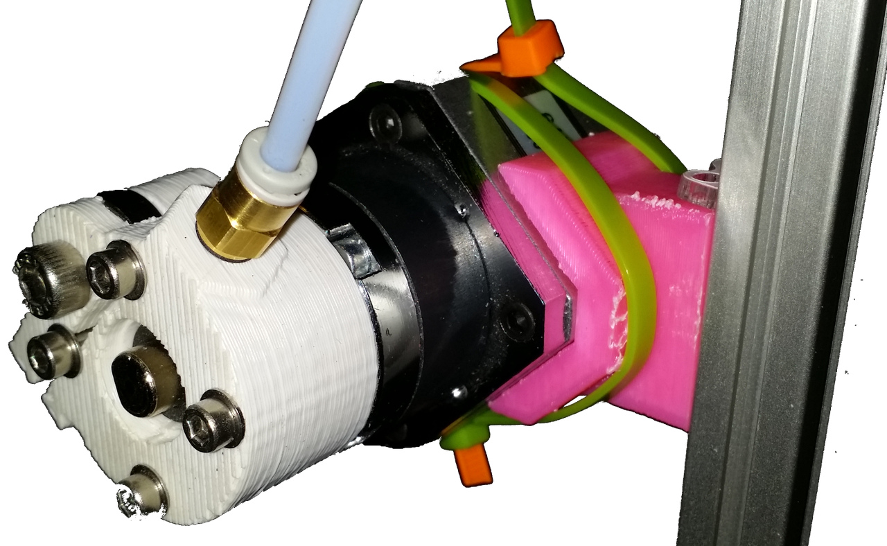
My Chinese version of what I think is a fairly standard Mark-IV J-Head hot end worked very well for the first couple of test prints, until the heater/resistor burned out. It seemed to be working very hard to maintain temperature.

I got several replacement resistors from Digikey, and tried a 3W 5.6 Ohm one (Panasonic ERX-3SJ5R6) which was similar in size. Same diameter, but a few MM shorter. Even with extra layers of rolled-up Kapton tape, to hold air-bubbles, it had trouble maintaining temperature while extruding with the fan on. It too burned out. I have some 4.7 Ohm, 3W of a similar size I can try, which should be able to deliver more power, but might burn out even easier. I also have one 5W, 5.6 Ohm, less likely to burn out, but no more powerful.

Small ceramic heaters, rated at 30W are on the way from China, but they could take a month or more to get here.

Adric from Quelab suggested using Melamine foam as insulation. This foam is commonly available as Mr. Clean “Magic Erasers”, or generic equivalents. I will be giving this a try.
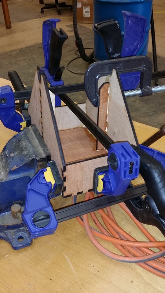
pronterface settings for delta bot

I have my slic3r set up so that the center of the part will be at the origin of the XY plane.

For pronterface to center these objects, I needed to go to Settings–>Options, Printer settings tab, check curcular build platform, and enter these settings:
pronterfaceSettings
Adjust Width, Depth, XY offset to match the size of your print area (slightly smaller than your print bed). The Height is from my MANUAL_Z_HOME_POS setting in Marlin/Configuration.h

Plots of Delta Bot distortions from common calibration errors

I write some Octave (MATLAB) scripts to model the delta bot commands and compute the actual effector position of a Delta bot. I can introduce errors to the Delta bot definition, and plot the results of its response to an ideal command. In this case, I am just raster scanning the bed of the printer.


When the DELtA_RADIUS is too small, we see center-low distortion (bowl), and XY scale expansion.
When the DELTA_RADIUS is too large, we get a center-up distortion (bra), and XY scale shrinkage.


When the rod length is longer than reported, we get a bowl (and shift down).
Rod length errors seem to be roughly half as sensitive as radius setting errors.
I intend to measure rod length carefully, and calibrate the radius setting only.


Tower position error causes this curve in the direction of the misplaced tower.


XY distortions are harder to plot. The tower shift does make some lines curve.
The grid points should all be equally spaced at 5mm.

I would recommend setting the compiled in MAX_Z setting at slightly less than your actual endstop height. You can use endstop offsets (M666) to adjust proper center location and home z-height.
Calibrate the compiled in DELTA_RADIUS setting to remove any bowl distortions.
The M666 endstop offsets should be able to remove tilt and potato-chip shaped distortions.

It might be worth the effort to write a script that runs a fast-converging optimization search algorithm that can adjust these four parameters. Unfortunately, since DELTA_RADIUS currently requires a re-compile, I can’t write a simple procedure. I am giving serious thought to putting a DELTA_RADIUS adjustment in the EEPROM which can be altered by an M code. The drawback is that Marlin uses macros for about 10 quantitles, all dependent on DELTA_RADIUS, so it will require replacing some of these macro number definitions with variables that need to be initialized at start-up.

Delta endstop calibration

I have been having some trouble with the delta 3d printer endstop calibration procedures.
It seems like something more formal might converge faster.

I question weather putting the effector in the center of the print bed is correct, given construction errors. My printer is unlikely to be perfectly symmetric and squared.

It seems to me that if things are centered, any bowl distortion should be uniform.
Hence, we should be able to calibrate the endstops by measuring the height of points in a commanded circle about the “center”, then adjusting the endstops such that those points would be at the same height on a properly calibrated printer.
For this procedure, some bowl distortion is expected. Try to calibrate for a flat, symetric bowl.

Alternate this flat-bowl calibration procedure, with adjustments to the DELTA_RADIUS to try and remove the bowl distortion. I will assume that the rod length can be accurately measured, so it will not be adjusted.

Command the effector to equally spaced positions around a circle, and note the actual Z height error at each position. Using calculate_delta.m, convert these Cartesian error positions to the Tower XYZ heights that should have been required to command to this measured Cartesian position.

Compute the mean of all of these tower positions, and subtract them from the current endstop offsets as set by M666 (and reported by M503).

Iterate on this procedure until until the commanded circle is flat.

You may wish to adjust by something like 0.9 or 0.6 times the computed adjustment to avid overcorrection.

I would recommend sampling 4 points, at (50,0,z0), (0,50,z0), (-50,0,z0) and (0,-50,z0) since these positions are easier to command.
If you wish, you could calibrate at points neareast to each tower, which should be (-43.3,-25,z0), (43.3,-25,z0) and (0,50,z0)

Delta 3D printer calibration with Marlin

I am not done calibrating my Kossel-Mini yet, but so far I’m finding a lot of coverage of the mechanical calibration procedure to be rather wordy and intimidating.
In retrospect, having made it part way through, it does not seem all that bad.

I moved the macros MANUAL_Z_HOME_POS and DELTA_RADIUS to the top of my Configuration.h, since they seem to be the main two variables that need tweaking.

MANUAL_Z_HOME_POS can be rather accurately estimated with a simple ruler. It is the distance from the extruder hot-end tip to the bed when in the home (top) position. I would enter a number a few mm larger than this into your MANUAL_Z_HOME_POS macro at first so that you have a little “working room” to adjust it.

DELTA_RADIUS appears to be the length of the XY projection of the diagonal rod, when the effector head is centered. I would estimate this at first with a ruler (or square).

I think that the setting of DELTA_DIAGONAL_ROD is fairly critical. This is the center-to-center distance of the holes at the ends of the diagonal push rods. Try to find somebody with good calipers to measure this as accurately as possible.


  • End stop calibration

    If the extruder tip is not at(near) the center of the print bed after homeing and moving in pure Z to a position just above the bed :
    1. Adjust the position of the endstops so that the extruder tip would be closer to the center.
    2. Re-Home, then move to a position just above the plate, at X=0, Y=0.
    3. repeat


  • Z-height calibration

    1. Home the effector.
    2. Command it to move a few mm above the center of the print bed
    3. Lower the print head (moving in -Z direction) until the extruder tip almost touches the glass (within 0.1mm or so).
    4. Read the extruder position (M114), and subtract the Z ordinate (which should be nearly 0) from the setting for MANUAL_Z_HOME_POS.
    5. Re-compile and upload with new MANUAL_Z_HOME_POS setting
    6. repeat until adjustment is (nearly) zero

  • Radius Calibration
    1. Move the head to a position slightly above the print bed and near the center, and measure the actual height above the print bed.
    2. Move the head towards the edge of the bed. A pure X-Y move, constant Z. Measure the true distance to the bed.
      • If the head is farther from the bed at the edges than the center, decrease DELTA_RADIUS.
      • If the head is closer to the bed at the edges than the center, increase DELTA_RADIUS.

    3. repeat


When the height and flattness are pretty good the residual error can be compensated for by the autoprobe procedure.

If there is not an M-code to set MANUAL_Z_HOME_POS and DELTA_RADIUS and save them to the EEPROM, I think there should be. Every time you do maintenance on the frame, belts, etc… these will need to be rechecked.


It may not be realistic to get the centering perfect by moving the endstops delta designs which do not have micro adjustment screws (like the Kossel-mini).
It would seem to me that once you have things centered fairly well, you could add G-code like:

G28 ; home
G91 G21 ; relative positioning in mm
G1 X-0.7 Y0.3 Z-0.4 ; adjust for error from imperfectly placed endstops
G92 X0 Y0 Z0 ; make this position the new home
G90 ; return to absolute positioning

to your homing operation.

Upon reading some discussions on “proper” generic G-code, I think that this should also be valid:

G21 ; make sure we are in mm
G28 ; home
G91 G28 X-0.7 Y0.3 Z-0.4 ; set proper HOME to this relative dist from G28 sensed HOME
G90 ; return to absolute positioning

If there is not a place in pronterface to define this homing procedure, it might be nice to get it into the delta firmware somehow. It would make sense that the above XYZ home offset would be among the parameters updatable by M-code, and saved in the EEPROM.

Filament Spool Holder


spoolHolderThe following drawing is for a laser-cut thin-plywood holder for 3D printer filament spools.  Just get some 1/2″ PVC pipe or conduit with endcaps for an axle to hold the spools.

When cutting this design in cheap 5mm furniture backing, there were problems with the warping of the stock.  Our laser cutter needs a very flat surface to cut.  I have had to split the design into smaller cuts, which fit on smaller pieces of stock.  The warping error across a small piece of stock can be much less than the warping across a piece of stock large enough for the entire design.

The drawing was split into the


bottom and edge
parts,

which should be cut once, and the


triangular side panel
,

which should be cut twice.


I posted this picture thinking the number of clamps I was using was silly.

clampsI was informed by a pro that this is actually a proper procedure.

Extruder Motor Mount

bowdenExtruderMount

Installed new Bowden extruder motor mount to vertical frame leg.  Bracket has very tight tolerance to the NEMA17 motor body, so that the motor almost snaps into the mount.  The attachment is actually very solid, even though it is made by wrapping some cable ties around the motor in an “X” pattern.  It mounts to the 15mm wide extrusion rail with two 8mm M3 hex-head bolts, and two standard M3 nuts in the rail.

Clearance from rail is enough to allow linear slider wheels to pass by.

Drawing is available from my github area.

Stepper motor wiring

WiringThis is the diagram for wiring the stepper motors to a RAMPS shield.  I am a bit confused.  I thought that each pair of leads (left to right pairs) on the groups of four were leads to a single winding.  Why would they want to swap leads (chaining windings together?) on the main drive motors?  Note that all of these driver boards have all three jumpers installed.  AFAIK, this setting just made steps smaller.

Also, why swap outside leads on the extruder motor?

Leads on the RAMPS board are labeled (in order), 2B 2A 1A 1B.  I was thinking that 1 and 2 refer to windings, and A and B refer to which side of the winding.

My NEMA17 motors have Blue, Yellow, Green, Red wires (in that order).  How might that correspond to the Blue, Green, Red, Black wires shown for these motors?  Is it possible that the flipping is only needed for their brand of motor, and not for mine?  If their brand of motor is different from mine, could the swapping be necessary to put the leads for each winding on the appropriate pins, whereas for my brand the swap is unnecessary?  Their drawing might make sense if the motor did not put leads for the same winding next to each other.

On my motors, the Blue and Yellow leads show 2.7 Ohms, and the Red and Green leads show 2.7 Ohms, so those look like winding pairs.  (Blue or Yellow) to (Red or Green) show no connection.   My best guess is that I don’t need any “wire flipping” for these motors to a RAMPS board.  If the direction is wrong, I can just flip the plugs over, right?

New design for Delrin Wheel carriage for Kossel-mini delta 3D printer

Just finished a drawing for my latest delrin roller based carriage for a delta 3D printer.  This one uses hardware-free toothed belt clips.  You should be able to attach the belt with no tools or hardware.  Just wrap the belt, teeth toward the “teardrop”, such that the teeth mesh when the belt re-joins at the pointed end of the teardrop.  Insert this little teardrop shaped belt loop around the teardrop post, and it should hold tight.

delta carriage

Delrin wheel based carriage for Delta printer